
Magnetic Rotary Encoding

The method of detecting rotation that’s discussed on this page was born from my need for a rotary encoding solution that’s contactless, continuous, bidirectional, cheap, and easily customizable for different project types.
The goal of having contactless rotation detection is mainly to alleviate the wear and tear issues associated with contact-based rotary encoding components like potentiometers and rotary switches.
Functioning Principle
The main idea here is to attach magnets with alternating poles to the rotating body, and then use two hall effect sensors to read the analog value changes that occur when the body rotates. With this setup, the circuit/sensors are completely isolated and make no physical contact with the rotating body.

The animation above shows the basic operation of this setup, the outer ring with the alternating magnetic poles represents the moving body that revolves around two stationary hall effect sensors.
The placement of the sensors is based on an Angle (𝜃), which can be calculated using the formula:
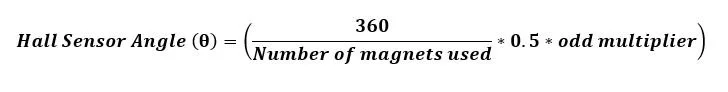
Where “odd multiplier” is an odd positive integer value that ensures the proper offset between the hall sensors, this value can also be used to customize the sensor arrangement in the containing system, I typically choose a value that gets me a separation angle around 90 degrees, but you can go as low as 3.
The “number of magnets used” must be an even number and 2x this number dictates the resulting resolution of the magnetic rotary encoder. Choosing a value that divides by 2 into an even number will result in a scalable encoder, meaning, you will be able to reduce or increase the encoder’s resolution by simply changing the number of magnets used.
For instance; a rotary encoder that’s designed to use 24 magnets which will result in an encoder resolution of 48, will also be able to use 8 magnets for an encoder resolution of 16 (scaled down), as well as 72 magnets for an encoder resolution of 144 (scaled up). You’ll notice that the common ratio is 3, which is an odd number that ensures that the offset between the sensors is maintained, so in theory, you can continue to multiply the number of magnets by 3 to get higher and higher encoder resolutions, provided the system permits it.
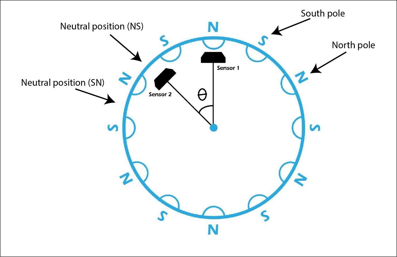
The angle (𝜃) calculated, offsets the sensors from each other in such a way that one of them will always be in the neutral position whenever the other is facing either of the poles. from this arrangement, the following truth tables can be derived.

The tables show the state of each sensor with respect to the other at any point in time.. so when sensor 1 is facing north, sensor 2 will be in the neutral position, which is represented as a zero on the tables. from that information, we can further deduce the state that represents one clockwise step and one anticlockwise step, based on the four possible start positions.
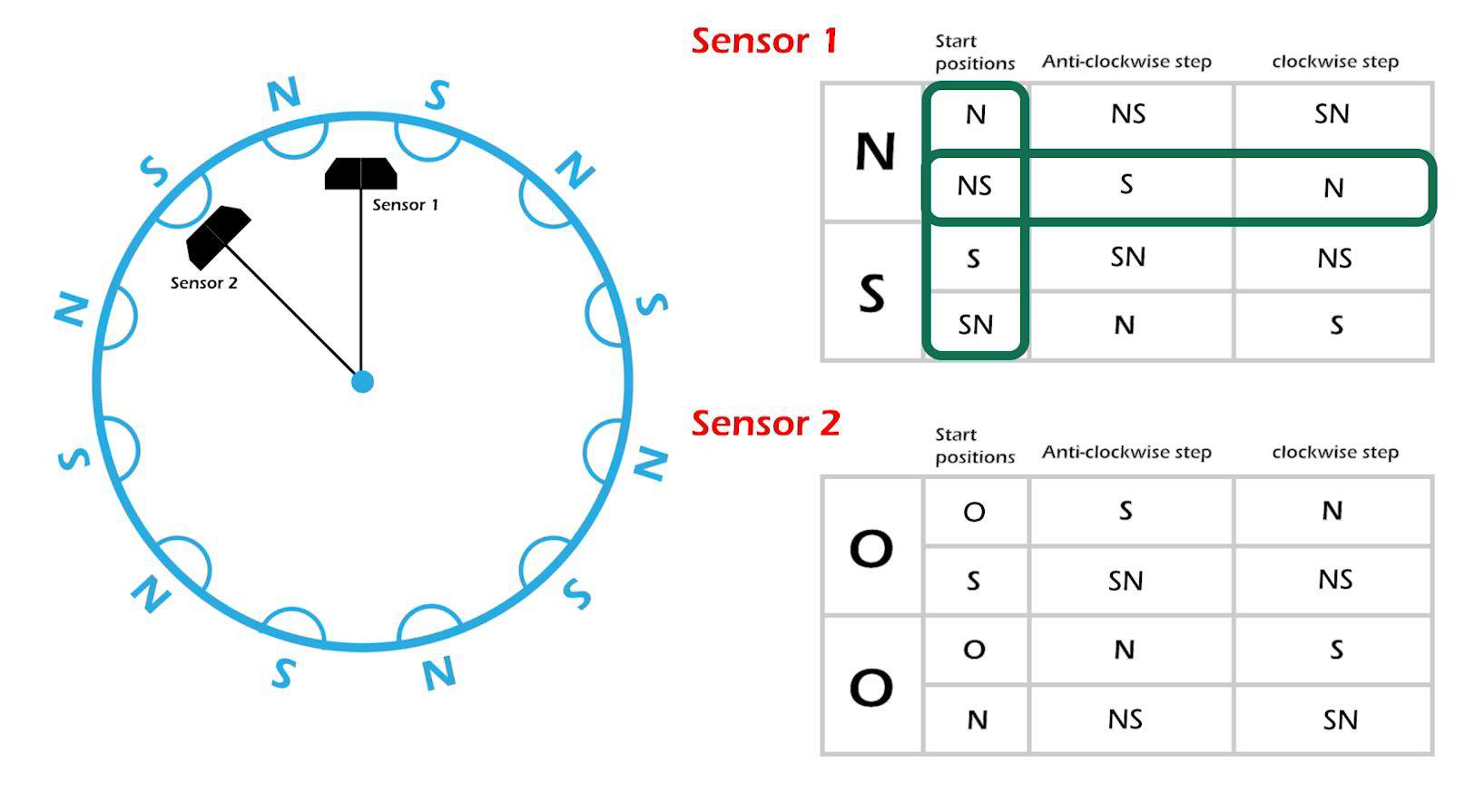
For instance, if sensor 1 is currently between N and S, Its clear that if its state changes to S, the outer ring must have moved one step anticlockwise and if its state changes to N, it must have moved one step clockwise.
let’s assume it did move clockwise to N, this becomes the new start position, and once again, one can tell that if its state changes to NS that’s an anticlockwise rotation, and if it changes to SN, a clockwise rotation.
The continuous repetition of this process is how the rotations are registered.
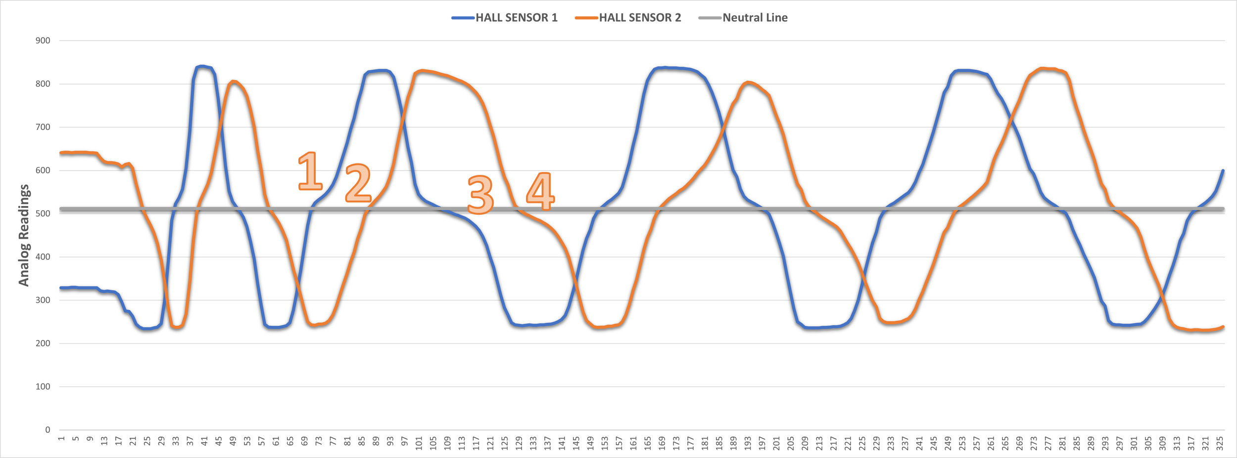
Another thing worth mentioning is the operation of the linear hall effect sensors used in this rotary encoding system; the range of analog values from the sensor is divided into two, so the lower half could be assigned to the North pole and the upper half to the South, or vice versa, the image below shows the magnet pole assignment for a 10 bit ADC system.
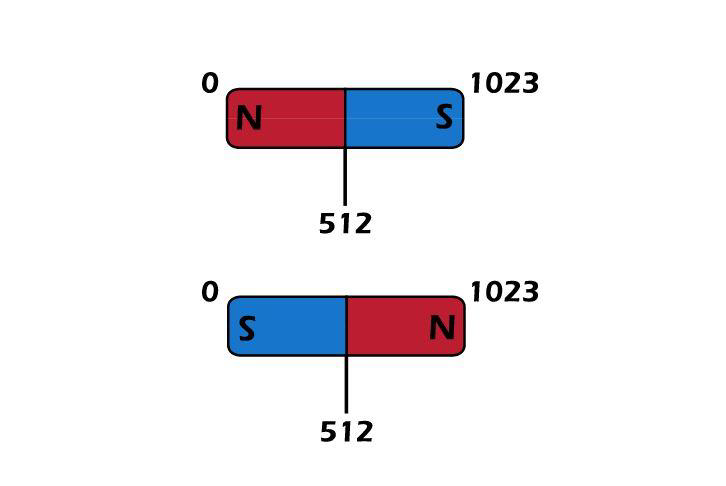
What this means is the middle position will always be the same value regardless of the orientation of the magnet, so NS, or SN, is all the same to the sensor, therefore all the “NS” and “SN” on the tables are all synonymous to the neutral position, this means each table only accounts for 50% of the data required to accurately detect the rotations… which is why this setup requires two hall sensors.

Interpolating for Higher Resolution
This magnetic rotary encoding uses linear hall effect sensors to determine the movement of the magnets and by extension, the rotation of the body holding said magnets, being an analog-based encoding method, this system allows for interpolation or micro-stepping between discrete steps for a much higher resolution than the encoder is designed for.
Taking a closer look at the alternating magnet arrangement that makes up the encoder, we can clearly see that there is a linear region between each pair of magnets, so there is a gradual transition from one encoding state to another (between steps).
The animation above shows the step transition in a 10-bit ADC system, so assuming that the ideal value that represents the south pole of a magnet being directly above one of the sensors at a design-specific distance is 770, and the ideal value when a sensor is halfway between adjacent magnets is 512, then the full theoretical resolution of a single step in this encoder is equal to the difference between the analog values that represent the two states that define the step; which in this case is 770 – 512, which is equal to 258.
To then calculate the full resolution of the encoder, we simply multiply 258 by the base resolution, so if the magnetic encoder is designed to have a base resolution of 60, then its full resolution using interpolation will be equal to 15,480 (258 * 60) or a step resolution of 0.023, this resolution is associated with integer interpolation, using fractional interpolation, the resolution can be as high as 60,000, which is pretty ridiculous for an encoder designed off of cheap magnets and all effect sensors.
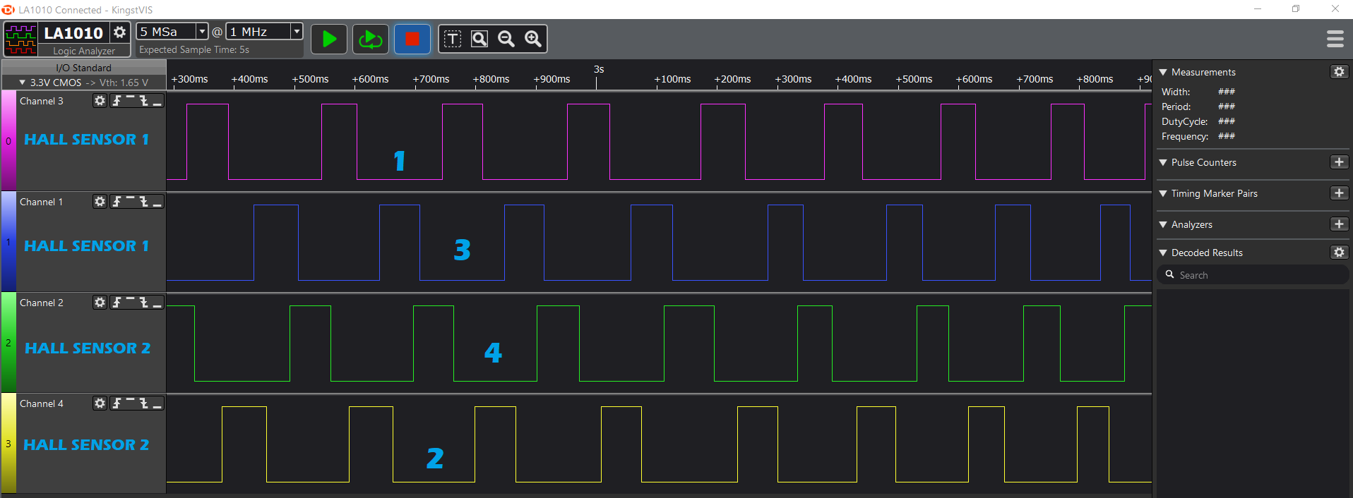
Doing Digital Encoding
As you may have guessed from all the mentions of ADC in this article, this rotary encoder relies heavily on analog to digital conversion, most microcontroller boards have analog to digital converter built in so, they can easily interface with the encoder, that said; ADCs are precious recourses and some projects may not be able to spare analog inputs for a rotary encoder; some microcontrollers don’t even have ADCs, to begin with.
With this in mind, it becomes necessary to come up with a way to covert each of the analog states in the encoder into useable digital signals.
This can be done easily using a Comparator circuit:
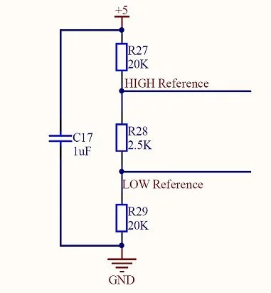
First, we define a voltage window that signifies when any of the Hall effect sensors is halfway between two opposing magnets so that any voltage reading that falls outside this window is considered to be either the North pole or the South pole of the magnet. This is done with a simple voltage divider network.
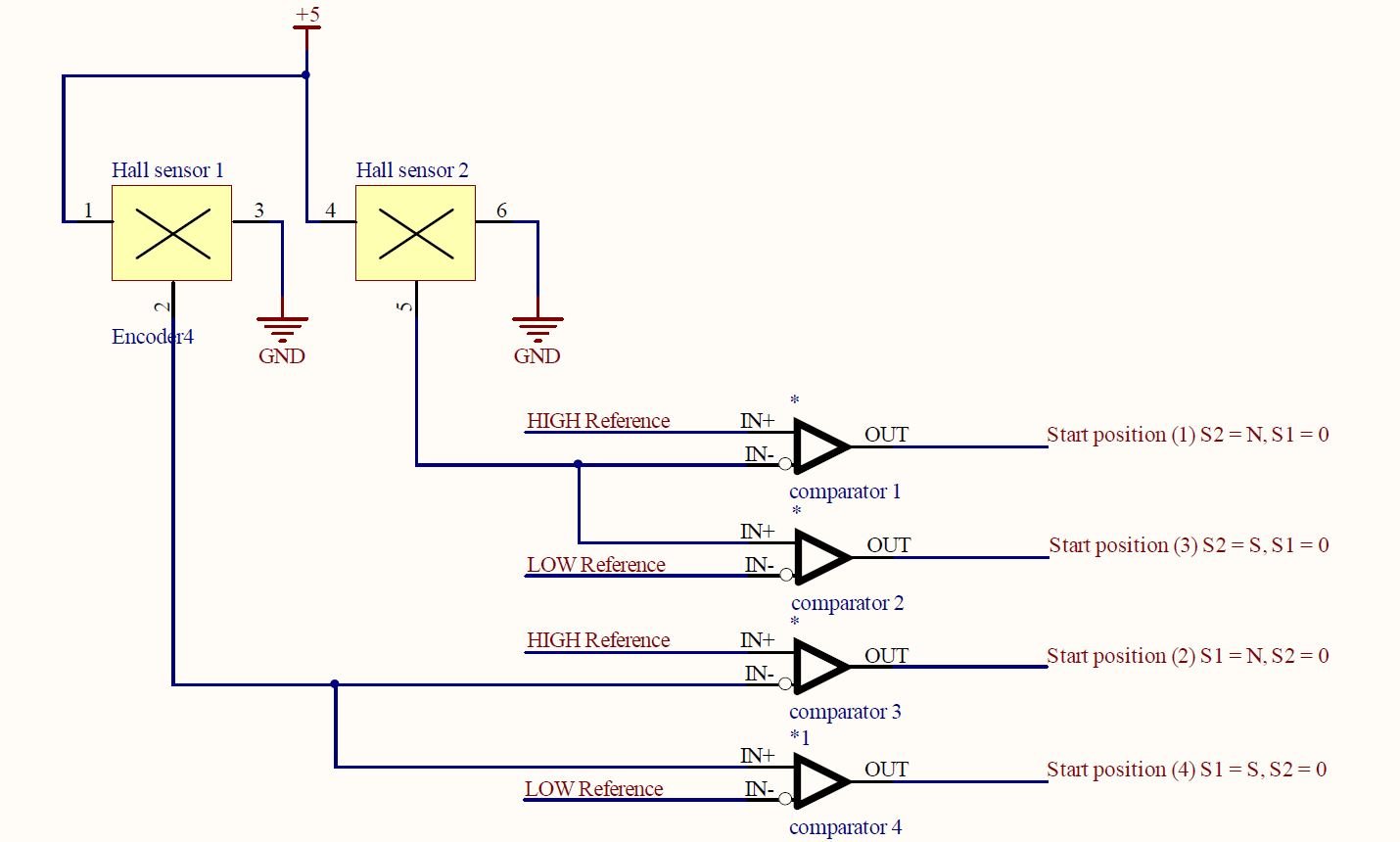
Second, We wire four comparator circuits, using the voltage divider window as a reference, and the signals from the hall effect sensor as the input. A comparator compares two analog values and outputs a digital high or low signal, depending on how it’s wired.
For a greater than (>) comparator, the reference voltage is connected to the inverting input and the input signal to be compared is connected to the non-inverting input of the comparator, for a less than (<) comparator, the inputs are interchanged, so reference to +ve and signal to -ve. With this connection, we can wire a pair of comparators to each of the hall effect sensors on the encoder to generate a digital signal that represents either the north pole or the south pole of the magnets, and consequently generate four digital signals that represent the four possible states of the magnetic rotary encoder.
Analog Domain
Digital Domain
Implementing the Magnetic Rotary Encoder
The magnetic rotary encoder project has matured a lot since its development two years ago, it has featured in a lot of my other projects like the Ahmsville Dial and the Pick N Place Wheel, I have also designed standalone encoder boards for easy integration into Arduino and MicroPython projects, so if you're looking for a ready-made solution, head to my Store, and also check out the GitHub repository.
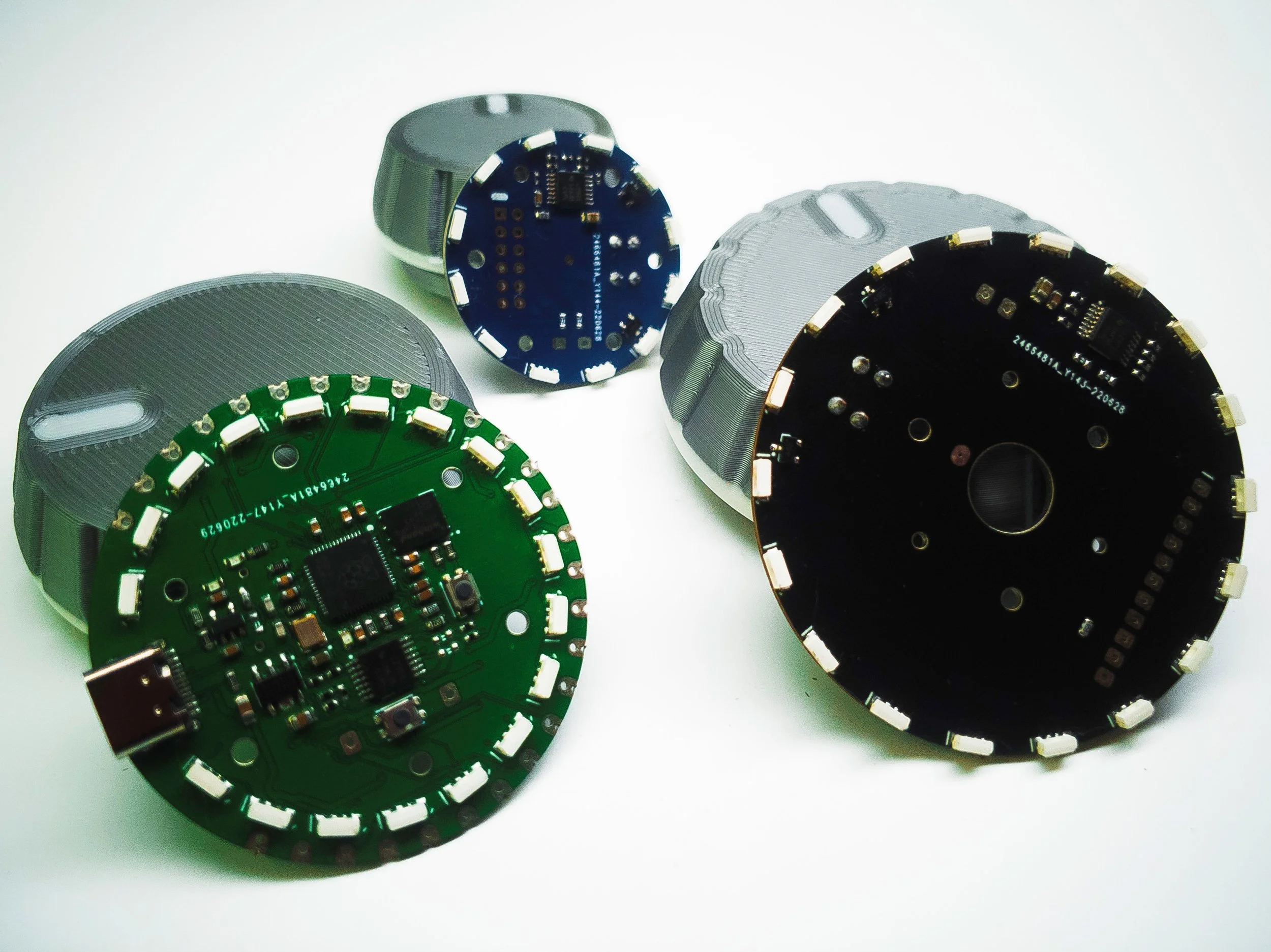
Magnetic Rotary Encoder Boards
For designers and developers like myself, the Magnetic Rotary encoder is an open-source project, with the source code, design, and manufacturing files at https://github.com/ahmsville/Magnetic_rotary_encoding