
The Pick 'N' Place Wheel
One of the things I’ve had to do a lot of over the last few years is designing and building PCBs, I had been looking for a way to make my PCB assembly process more efficient, and it wasn’t until I saw unexpected maker’s video on the pick and place turntable that he uses to populate his prototype PCB’s that it all came together, the concept of his design provided the bases for which I used to build the Pick'N'Place Wheel, so I’ll like to give a huge shout out to Sean from unexpected maker for sharing his idea and for inspiring the Pick'N'Place Wheel. Watch his video here.
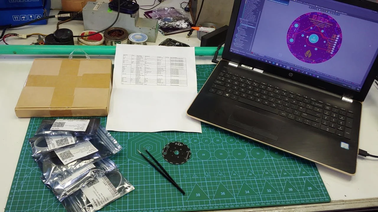
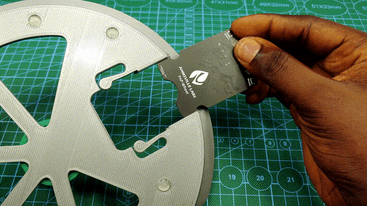
If you have ever hand-assembled a PCB, the setup shown in the picture will look familiar to you, to populate a PCB, I would normally have all the components on the table, along with the pre-pasted PCB and a spreadsheet for the board I intend to populate, this spreadsheet will usually contain important information like component value, footprint, designator and any other information that’ll enable me to accurately place the components. I would often also have my laptop close by so I can confirm the position on the board where specific components should be placed. With this process, I usually avoid placement errors, but the process can hardly be called efficient, especially when I have to assemble multiple PCBs.
My goal for the Pick'N'Place Wheel project is to combine all the elements associated with manual PCB assembly to form a system that is as seamless and as efficient as possible.
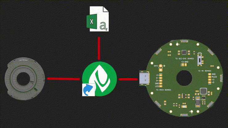
The Pick'N'Place Wheel is far from just a passive 3D printed device, it’s a combination of three main elements: The 3D printed wheel itself which is the hardware, the rotary encoding and slot indexing as the electronics, and the control software that ties it all together in the form of a desktop/web application. The Pick'N'Place Wheel experience will not be fully served without these three elements combined.
The Wheel
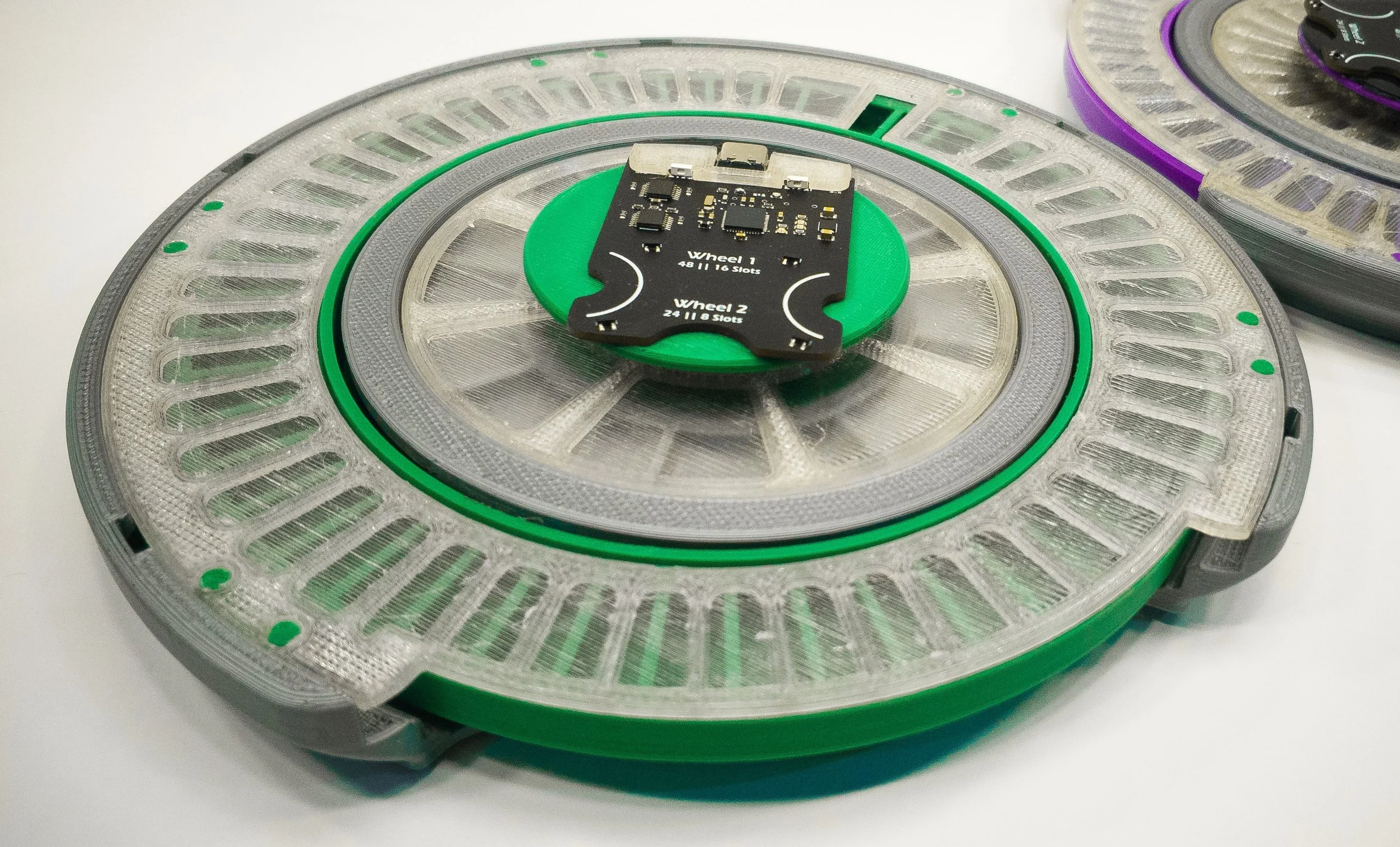
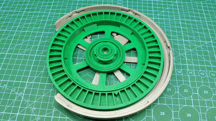
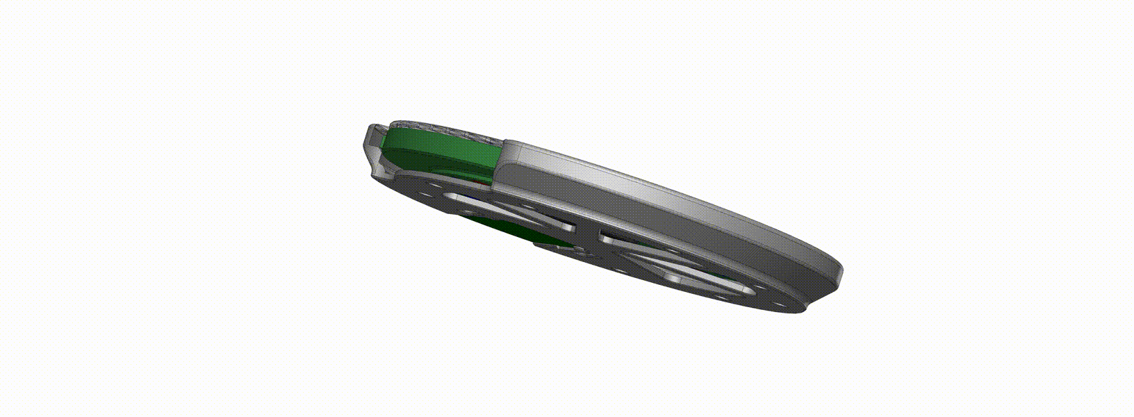
The wheel’s function is primarily to hold your components in indexed slots for when you're populating a PCB, but it also doubles as the permanent storage for those components, thanks to the built-in twist locking mechanism.
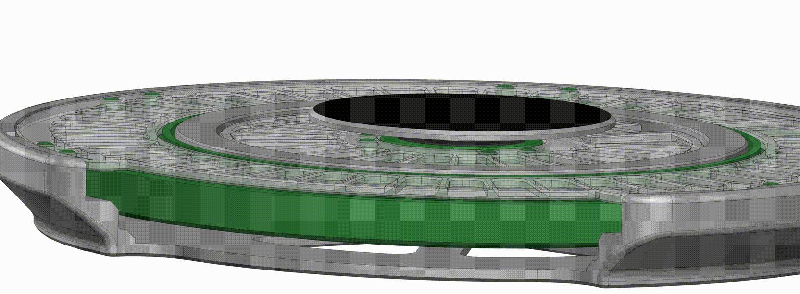
The wheel’s transparent top cover has a few flexible 3d printed tabs glued to it, these tabs fit into matching slots on the wheel’s base, so that when you turn the top cover in one direction it creates a 1mm separation from the wheel (opened state), allowing the wheels to rotate freely during board population, and when the wheel needs to be stored away, the cover can be turned in the other direction which lowers it back down unto the wheel (closed state), sealing the components in their slots and preventing them from falling out or falling into another component’s slot. So instead of keeping components in the anti-static bags that they came in, the Pick'N'Place Wheel can be used to index and store them.

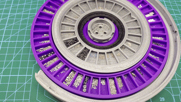
The Wheel is designed to hold two separately encoded wheels, one large outer wheel identified as wheel 1, and one smaller inner wheel identified as wheel 2. The image above shows the typical capacity of the wheel’s slots, each wheel has two versions, wheel 1 has a 48 and 16-slot version, and wheel 2 has a 24 and 8-slot version, these wheels can be combined in multiple ways to suit various types of PCB projects, the wheels with the higher slot counts are designed to hold a lot of small SMD components, while the wheels with the bigger slots are designed to hold bigger parts, like USB ports, LEDs, power inductors or connectors.
The placing surface where you’ll place the board you want to populate also has two versions to accommodate different board sizes. The image below shows all the possible configurations of the Pick'N'Place Wheel and their intended project types.

The Electronics
The Pick'N'Place Wheel is built around wheel encoding and indexing which is facilitated by the electronics.
Each slot on the wheel has an index, this index is used to identify and place the components that are stored in them, this is possible because the Pick'N'Place Wheel itself is one giant rotary encoder, or more accurately contains two rotary encoding wheels. The wheel uses the magnetic rotary encoding method that I developed a few years back, it’s the same rotary encoding that’s featured in the Ahmsville dial project.
Each wheel features a ring of magnets attached to its base which is configured with alternating poles, the magnets encode the slots on the wheels, so the number of magnets on each wheel is proportional to the number of slots on the wheels. The accompanying custom PCB has four hall effect sensors on it, which are used to read and interprets the analog values from the magnets as the wheels rotate, the resulting encoding data is how the slots get their indexes.
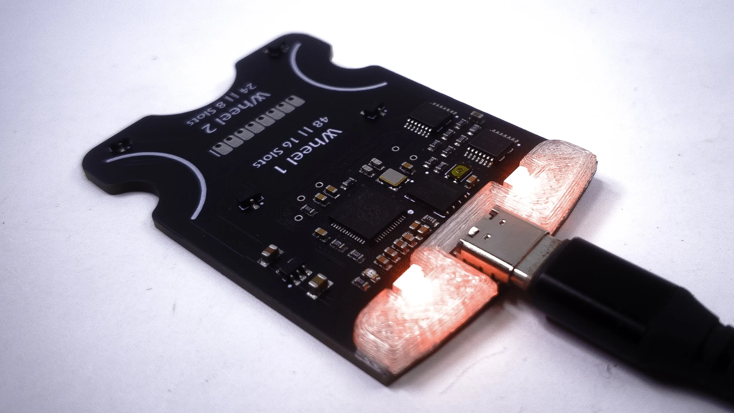
The board is a typical microcontroller board, it features four hall effect sensors for reading the analog values from the wheels, two analog comparators for ensuring accurate encoding of the wheel’s rotations, and two addressable LEDs that show the status of the wheels, the board is controlled by the RP2040 chip, the same as the Raspberry pi pico boards.
To keep with the modular theme of the Pick'N'Place Wheel, the board is also detachable, which means you can make as many wheels as you like, and you’ll really only need one board, since you can easily swap the boards from one wheel to the other, the board also supports all the different physical configurations of the Wheel.
The Application
The Pick'N'Place Wheel application (Desktop and Web) is the most important part of this project, the Pick'N'Place Wheel is all about simplifying the manual pick and place process and the software is integral to achieving this goal.
Whenever you’re populating a PCB, there are two main things you need to know, the first is the specifications of the component you’re about to place, like its value and its footprint, and the second thing you need to know is the location on the PCB where the component should be placed, this is where the software comes in, it uses the actual pick and place data generated for your specific board together with the image of the board to create pointers that tell you where and how to place parts on the board, this in conjunction with the position information from the wheel is what constitutes the complete pick’n’place wheel solution.
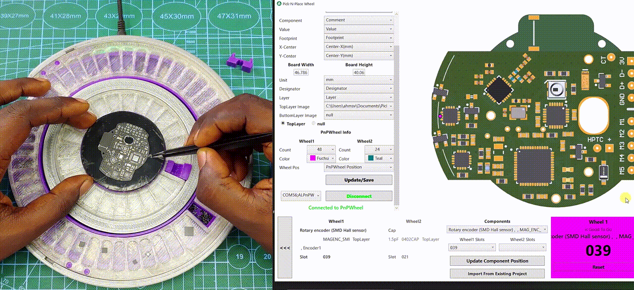
For every PCB you design, you’ll usually have the option to generate a pick and place file, this file will contain information like component name, value, and footprint but most importantly, it will contain the x and y position for all the components on the board. The second thing you can easily generate from your PCB design is a 2d image of the board, most PCB design software will allow you to preview your PCB in 3D, from this realistic 3d view you can easily generate an image that accurately represents the board, the image doesn’t have to be the same size as the board, it just needs to be in the same aspect ratio as the actual board. When you load the pick and place CSV and the board image into the app, it reads all the data from the CSV and also displays the image of the board.
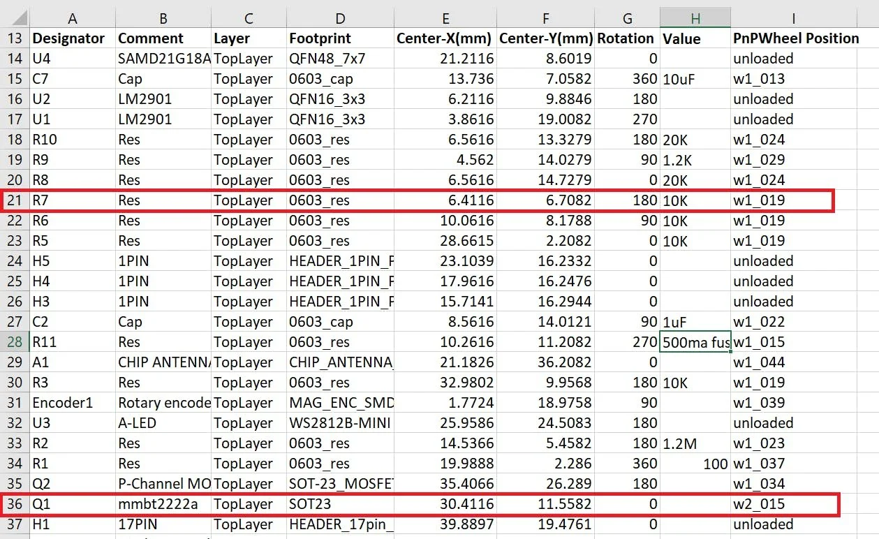
Whenever you load a new CSV into the app, a new column is created inside of that csv, this column is titled PnPWheel Position, this column is where the slot indexes for the components are stored, and the position information from this column is also what connects the physical Pick'N'Place Wheel to the app. so you’ll notice from the image that some of the rows say “unloaded” indicating that those components don’t have an index in the Pick'N'Place Wheel, the components that have been loaded into the wheel will have their index shown under the column, so row 21, for example, tells me I have 10kohms 0603 resistors in slot 19 of wheel 1 and row 36 tells me I have 2222A transistors in slot 15 of wheel 2. All the information used and displayed by the app comes from this one CSV file, the app only makes it easy to visualize and manage all the data in relation to the specific board.
During the actual pick and place process, the Pick'N'Place Wheel connects to the app through the serial port, and sends the slot indexes to the app as a string through serial communication, the app then uses that index to pull all the information about the component from the CSV, and then shows you all the information you need in order to confidently populate your desired PCB.
Using The Pick’N’Place Wheel
Depending on when you read this article, I would have been using the pick’n’place wheel exclusively to make all my PCBs for about 13 months, and I’ll tell you right now; I am never going back. the wheel has made my PCB assembly process almost entirely robotic, meaning the only thing I have to do is pick the components out of their slots in the wheel and place them where the app tells me with zero cerebral effort. If I populate a new PCB design that does not work as intended, I know with near absolute certainty that component placement is not the problem which makes the process of troubleshooting my boards more direct and predictable; if you misplace or omit a component earlier in the board population, the wheel app will help to catch it when it generates a pointer to a component that you should have not yet placed or to a component that you have passed on the wheel.
Labels are also not needed with the pick’n’place wheel as the app knows where all the components are stored on the wheel, I personally use the larger pick’n’place wheel XL which has 108 slots in total, this holds all the individual components in my collection with some slots to spare, asides from having to refill some components from time to time, I am covered with the wheel for all my foreseeable future designs.
Speaking of refilling, one of the recent features I’ve implemented in the app is inventory management, whenever you load a component into the wheel, it will ask you for the quantity, with this value the app keeps a master components sheet with the exact count of all the components in the wheel’s slots, you can refer to this sheet whenever you need to restock on components, so no more buying excess parts or manually counting components. you can learn more about this feature in the video.
I have also found that the pick’n’place system offers a really convenient way to share projects with others, if you design a PCB and you want to share it with someone else to replicate, all you have to do is send them the pick n place CSV and the image of the board, the person can then load this files into the pick’n’place wheel app, where they will be able to see all the specifications of the components featured on the board as well as their placement positions, you don’t even need to have the physical wheel to be able to do this, I myself have started sharing my projects in this way, so you’ll find a pick’n’place wheel folder attached to my projects on Github.
Notes:
There are two sizes of the wheel, the Normal size Pick'N'Place Wheel requires a 3D printer with at least a 200 x 200mm Bed size, while the larger Pick'N'Place Wheel XL requires a printing size of 300 x 300mm.
The Pick'N'Place Wheel App has two versions, a Desktop version for Windows PCs only, and a Web version for Windows, Mac and Linux (incl Raspberry Pi).
For instructions on how to setup the pick'n'place wheel app on a Raspberry Pi head to - https://www.hackster.io/ahmsville/pick-n-place-wheel-raspberry-pi-setup-088d0d